Clean, Safe, Perpetual & Free
Photovoltaic |
At www.mikebaker.com, we run a 6,000 watt clean energy, solar electric generating system.
The installation is comprised of
The system has two 'inverters'. These 'inverters' convert the D.C. electricity generated by the solar panels into regular house A.C. electricity.
Each inverter is 'fed' by 20 PV solar panels.
Sets of ten PV panels are wired in series to form a 'string'. There are a total of four of these 'strings'.
Two of these 'strings' are connected in parallel to each inverter.
The system is hooked up as a 'grid tie' system. The system connects to, and feeds into the regular home A.C. electric wiring through circuit breakers in the regular home fuse box. During periods when the electricity generated by the panels exceeds consumption, the electric meter runs backward. At peak production, the system makes enough electricity to fully power the central air-conditioning and have enough extra to make the meter run backward! At night (when the panels don't generate), I again become a regular electricity consumer.
Jersey Central Power and Light Co. is the major contributor to the purchase of the system. The rebate program under which I purchased and installed this installation reimburses me, up to, 70% of the system cost! As of this writing (Sept, '02), money is still available under this program (New Jersey, less than 10KW systems).
My system would not exist without this substantial rebate from Jersey Central Power and Light
The initial energy survey revealed
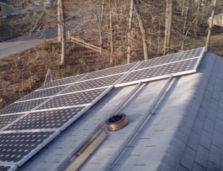
| My primary roof is large enough to hold three rows with nine panels per row. This picture was taken when we had 20 panels installed. | |
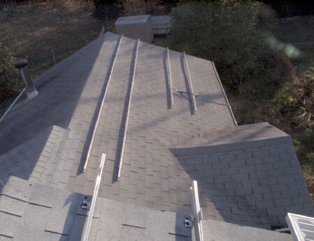
| Pairs of rails are the mounts for the panels. This picture is looking from my primary roof towards the secondary roof. | |
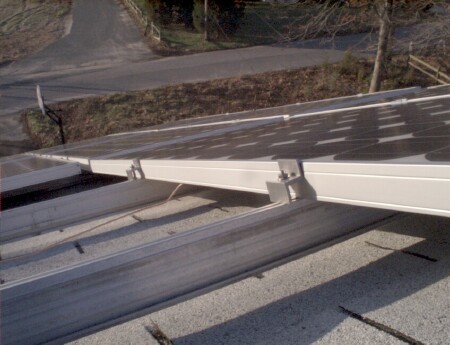
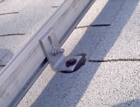
| The end panel of each row is held in place by a 'Z' shaped clamp that has a protruding 'hook' to hold the panel. | |
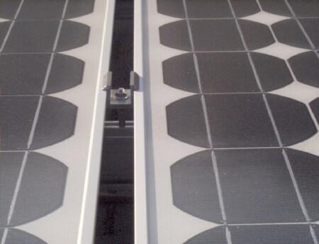
| The clamps used between panels has the same 'hook' on each side to hold the adjacent panels. | |
| The mounting rails are fastened onto 'L' brackets which are fastened to the roof rafters with lag screws. A couple of the rafters wanted to be elusive but we found them anyway. Standard 'stud finders' are challenged by the variations caused by shingles and roofing nails. The primary means of locating rafter position evolved into use of the tape measure. The lower roof was older construction (irregular rafter spacing) and each rafter position was measured individually from inside the attic. | |
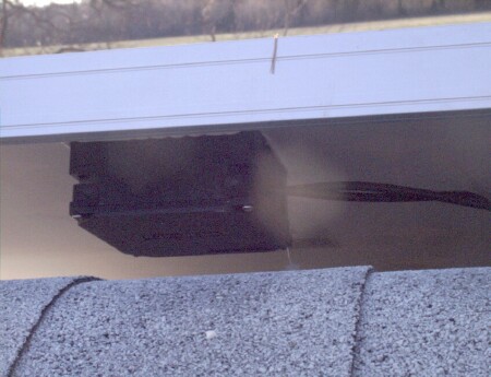
| A box behind each panel is where the wires are attached. The picture shows two wires. One wire goes to the panel on the left and the other goes to the panel on the right, forming a series connection. The Sunny Boy inverter used required that we would wire ten panels in each series. | |
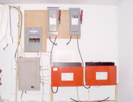
| The house AC breaker box, is on an end wall of the laundry room. It is the large dark gray box in the lower left corner of the picture. It was already full so I added a satellite breaker box above it. The tall narrow boxes with the big red handles, top center, are the DC breaker boxes. The red boxes at the bottom right are the Sunny Boy 2500U inverters. The AC wire coming out of the inverter, goes through the wall to outside, where the AC disconnect box is located (available to the utility company linemen). The small wire along the right side of the picture, is the RS485 communication wire which goes up, through the ceiling, to my 'office' in the room directly above. | |